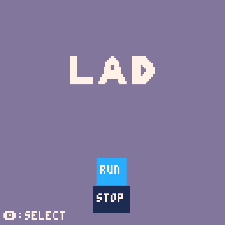
Ladder programing game prototype
Level 3 text at the bottom
Welcome to ladder programing. A visual, easy programing language available in all commercial PLCs (programable logic controllers). The language is described by the IEC standard but most vendors put their own spin on it.
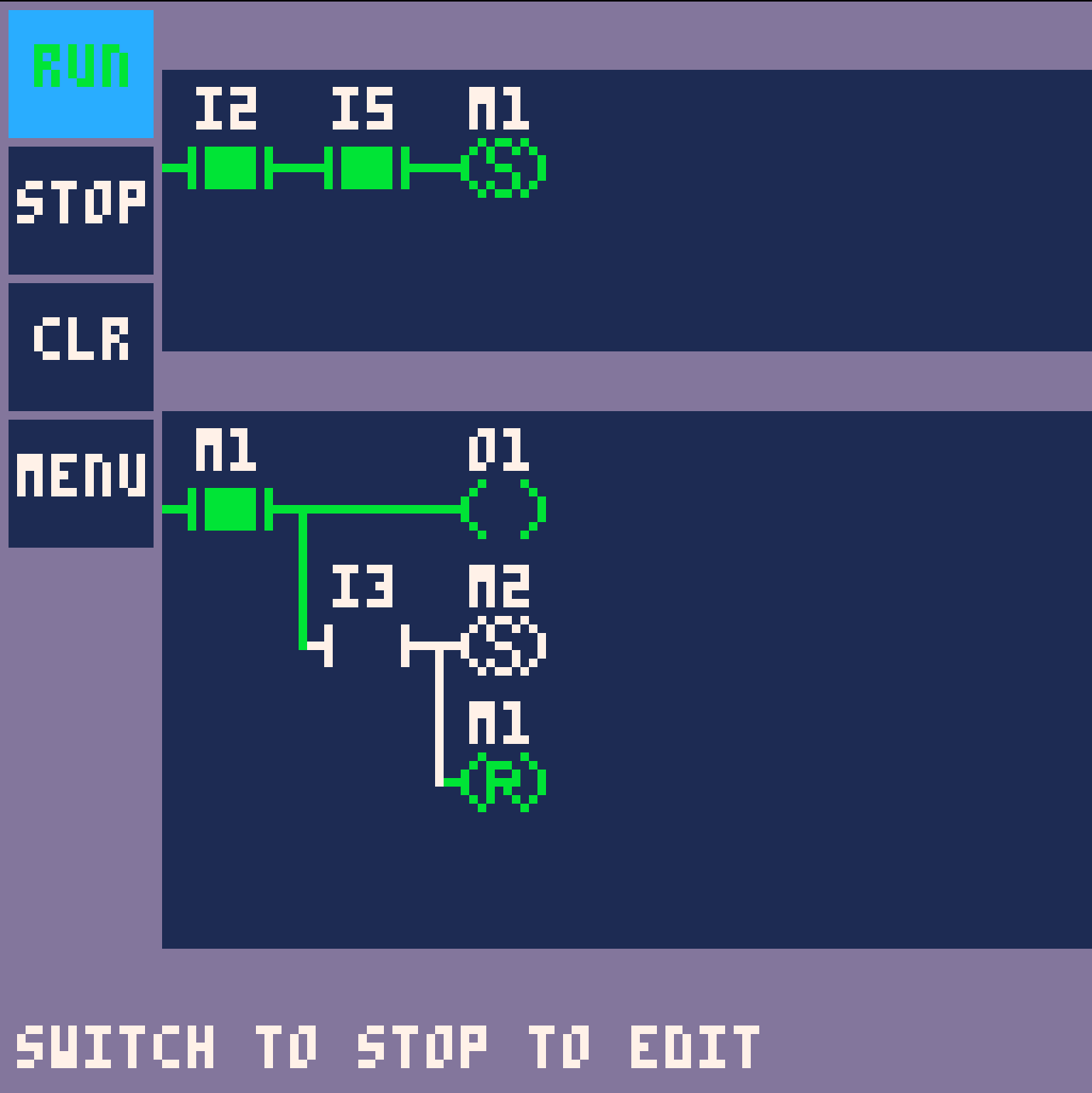
The program is represented by networks of contacts and coils. On the left of the network is the source, the highs signal. Contact either let the signal "pass" further towards the coils or stop it. Coils execute an instruction.
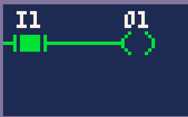
The program
The contacts and coils link to simple bits, variables that can hold a simple true or false value (bool). The game offers 3 types of bits. I type represents and input from outside the theoretical PLC. O type represents an output of the theoretical PLC. M type are internal memory bits that can be used to represent say a step of execution that the plc is in. The program is executed from left to right, top to bottom every frame. The output is updated at the end of the scan.
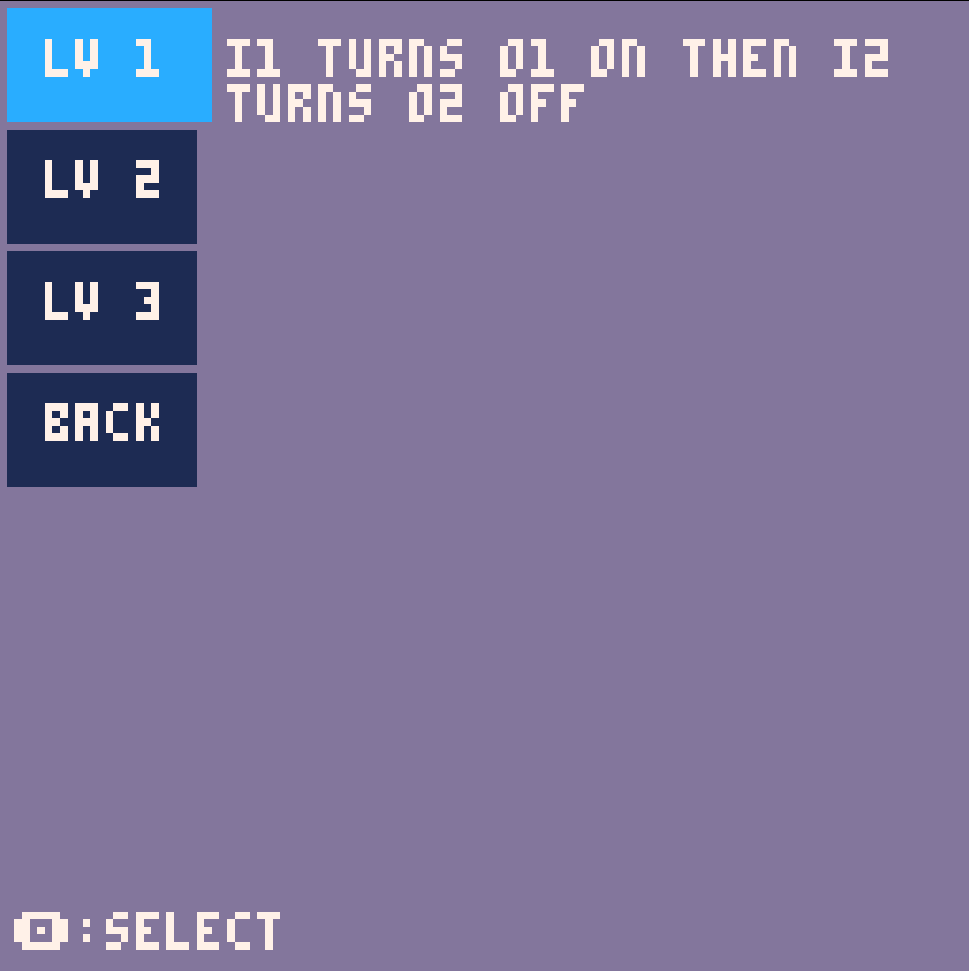
The prototype is level based, for the first 2 levels the request is written in game, for the 3rd level you have to look here.
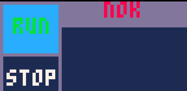
While in a level if your are on the left most column of any network you can hit left arrow to select the UI elements.
Hitting run will start the simulation and test your program. The conclusion of the test will be displayed at the top of the window.
Adding contacts and coils
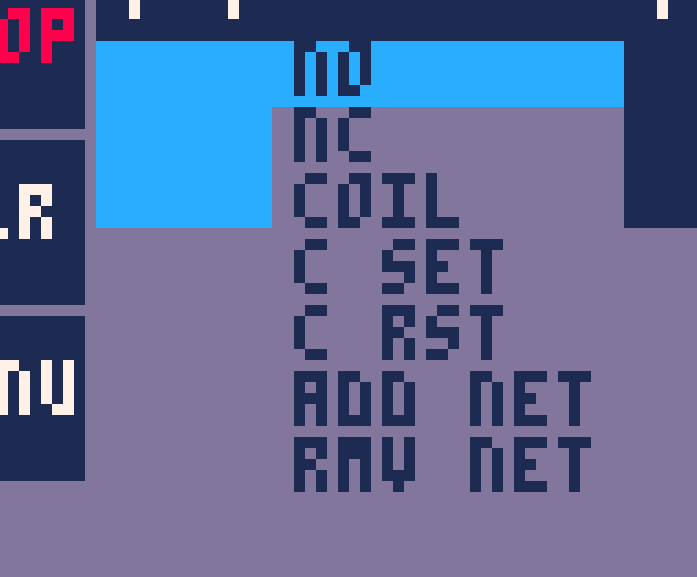
Contact and coil are created using the context menu. The coil context menu is open by navigating with the cursor ( the light blue square) over an empty field and hitting the Pico8 "o" button. Menu is closed by hitting "x".
Contacts
NO will create a normal-open contact node, for a NO contact if the value of the associated tag is LOW the contact is open, if the value is HIGH, the contact is closed.
NC will create a normal-closed contact. A NC contact is closed when associated tag is LOW and open when tag is HIGH.
COIL will create a coil node. If the input of the coli is high, the associated tags value will be set to high every scan, if the coils input is low the value of the tag will be set to low.
C SET and C RST are Set and Reset Coils. If the input of a set coil is HIGH then the associated tags value is set to HIGH. If the input of a Reset coil is HIGH then the associated tags value is set to LOW. Nothing happens if this coils input is LOW.
ADD NET adds another network.
RMV NET removes the network the cursor is on. This action can not be undone.
Assigning tags
Tag assignment is done through the node context menu. It is open by pressing "o" over a contact or coil.
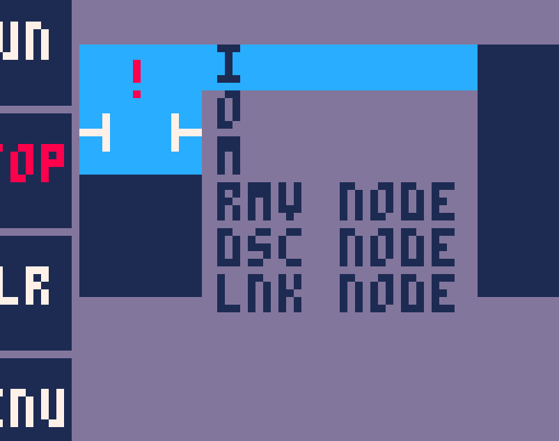
I, O and M open the lists of tags available. As mentioned above Is are inputs, Os are outputs and Ms are internal memory bits.
RMV NODE removes the node the cursor is on
DSC NODE removes any connections to other nodes the node at the cursor has
LNK NODE enters linking mode. In linking mode you chose what node you want to connect to the node you had your cursor on. You must choose the node the connection is meant to be made to, not the wire.
Level 3 guide
Level 3 simulates the basic operation of a marking machine.
The order of operations is:
- Operator loads part and pushes start button
- Doors should start closing
- When doors are closed, marking should start
- After the marking is done, the doors should open
- Operator takes out part
Input maping:
- i2 start button
- i3 doors closed
- i4 marking done
- i5 part present
Output maping;
- o1 close doors
- o2 open doors
- o3 start marking
- o4 stop Marking
Leave a comment
Log in with itch.io to leave a comment.